I Modded a CRT and Didn't Die from Electric Shock
Published
I got a Trinitron KV-36XBR200 a month or so back. Thing's an absolute unit. The chrominance on composite/S-Video inputs doesn't seem to quite work on the main output (works fine in picture-in-picture/picture-and-picture) so I decided to do an RGB mod to work around that issue in the meantime.
I got a mod kit from Sunthar for the similar KV-27V20 and a copy of the service manual from archive.org. I would have zero clue how to do any of this otherwise.
Assembling the Board
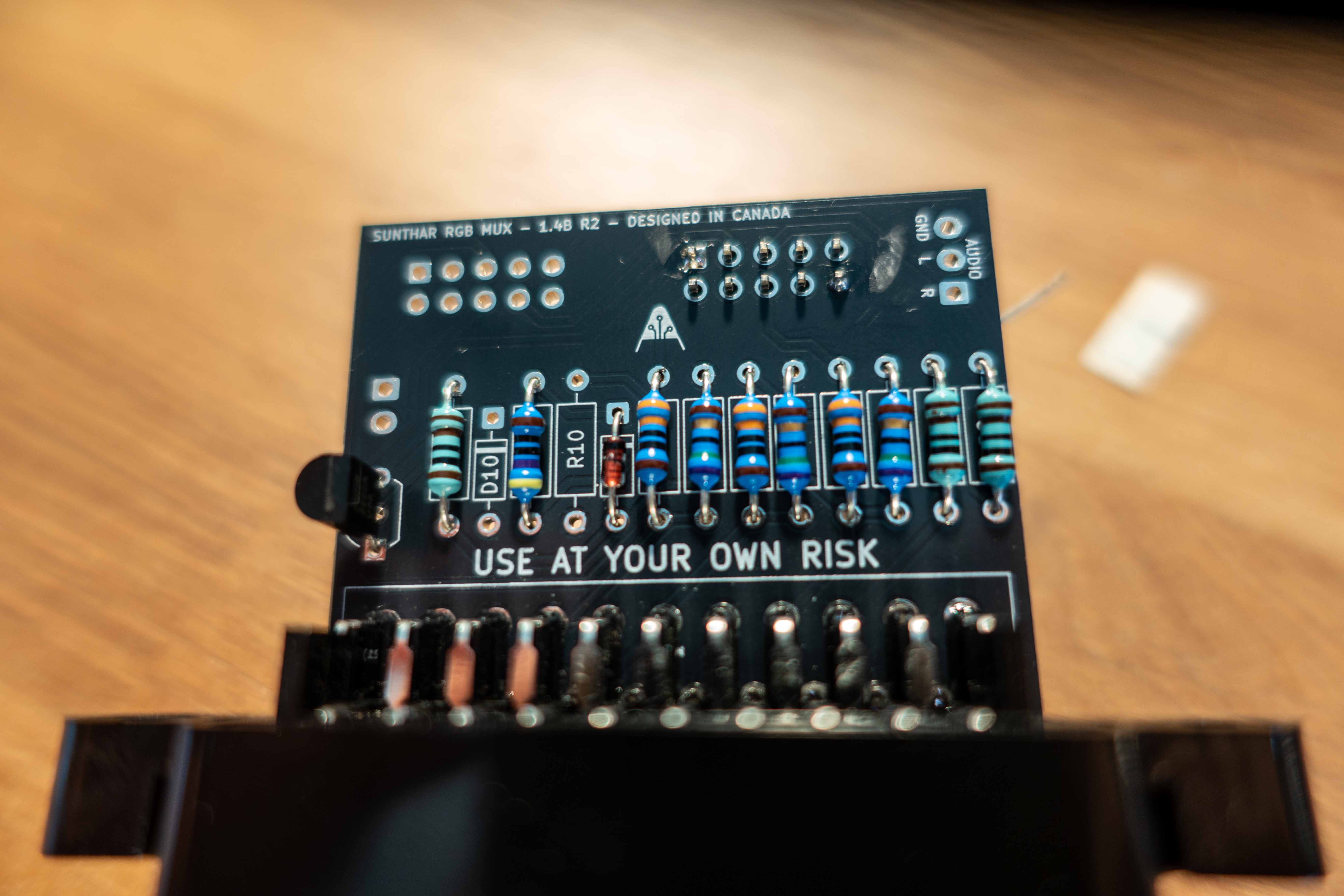
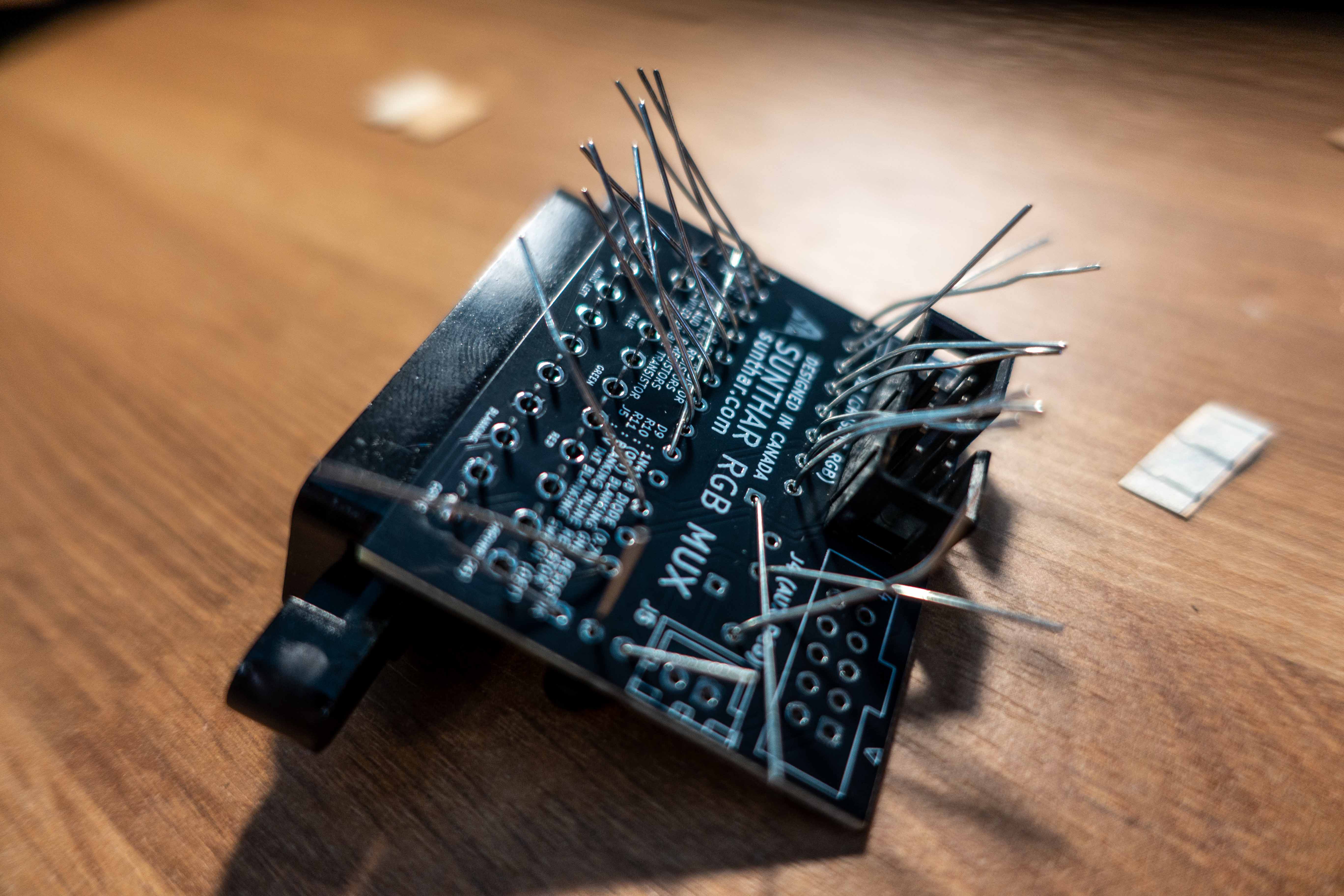
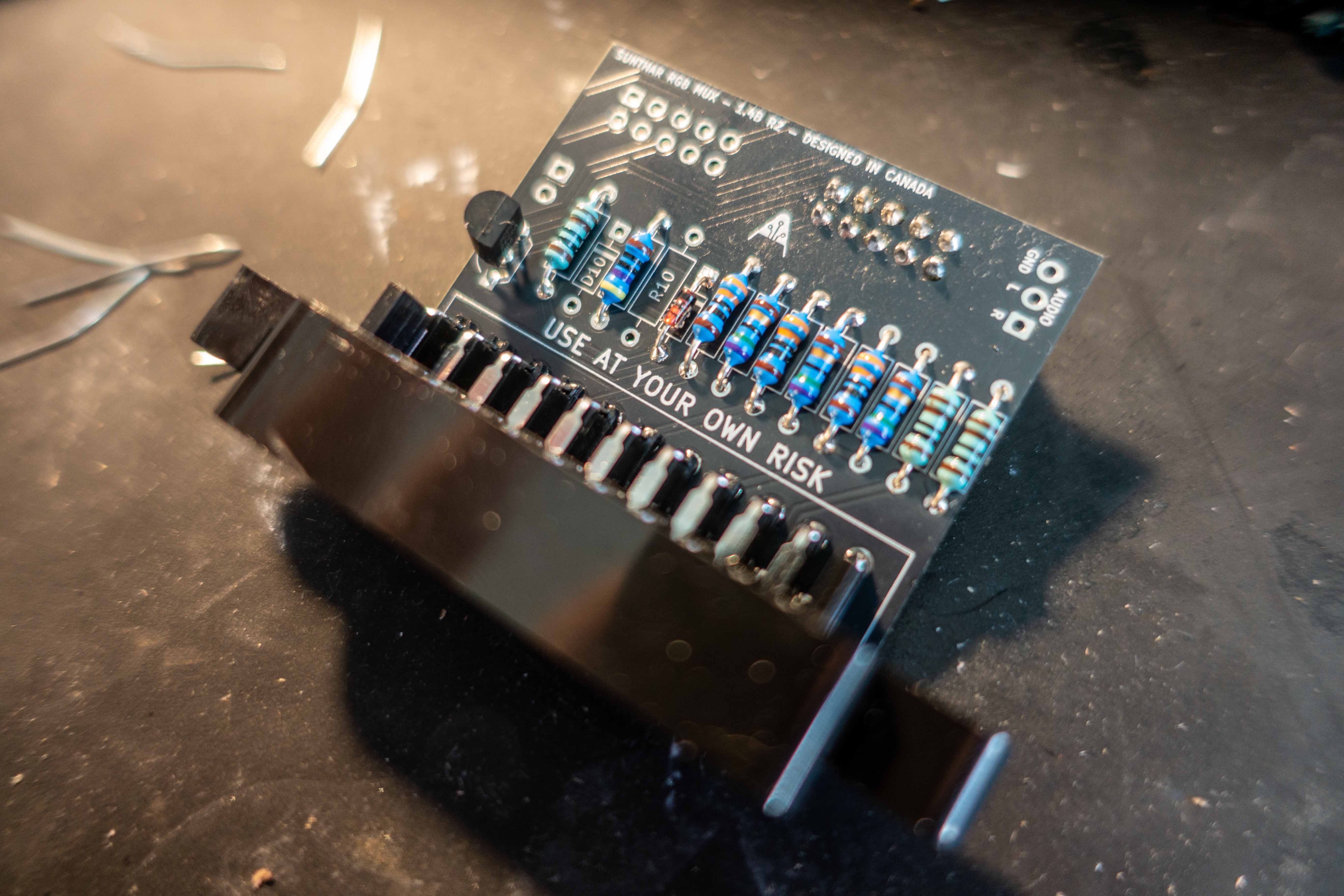
Populating the mod board itself was easy because everything was through-hole and all of the resistors, diodes, and transistors needed were known and documented on Sunthar's site. I went back and added a bit more solder to the parts here that were a bit low before installing the board - my eyes are definitely starting to have a harder time catching this stuff.
Gaining Access
This is where the fun begins. Getting boards out of the CRT was pretty nerve-wracking as I've never really worked around any voltages higher than US Residential AC before. It was pretty neat how Sony designed all these boards to elegantly slide out of the rear. Here I got a glimpse at a crack on the A board PCB - more on that later.
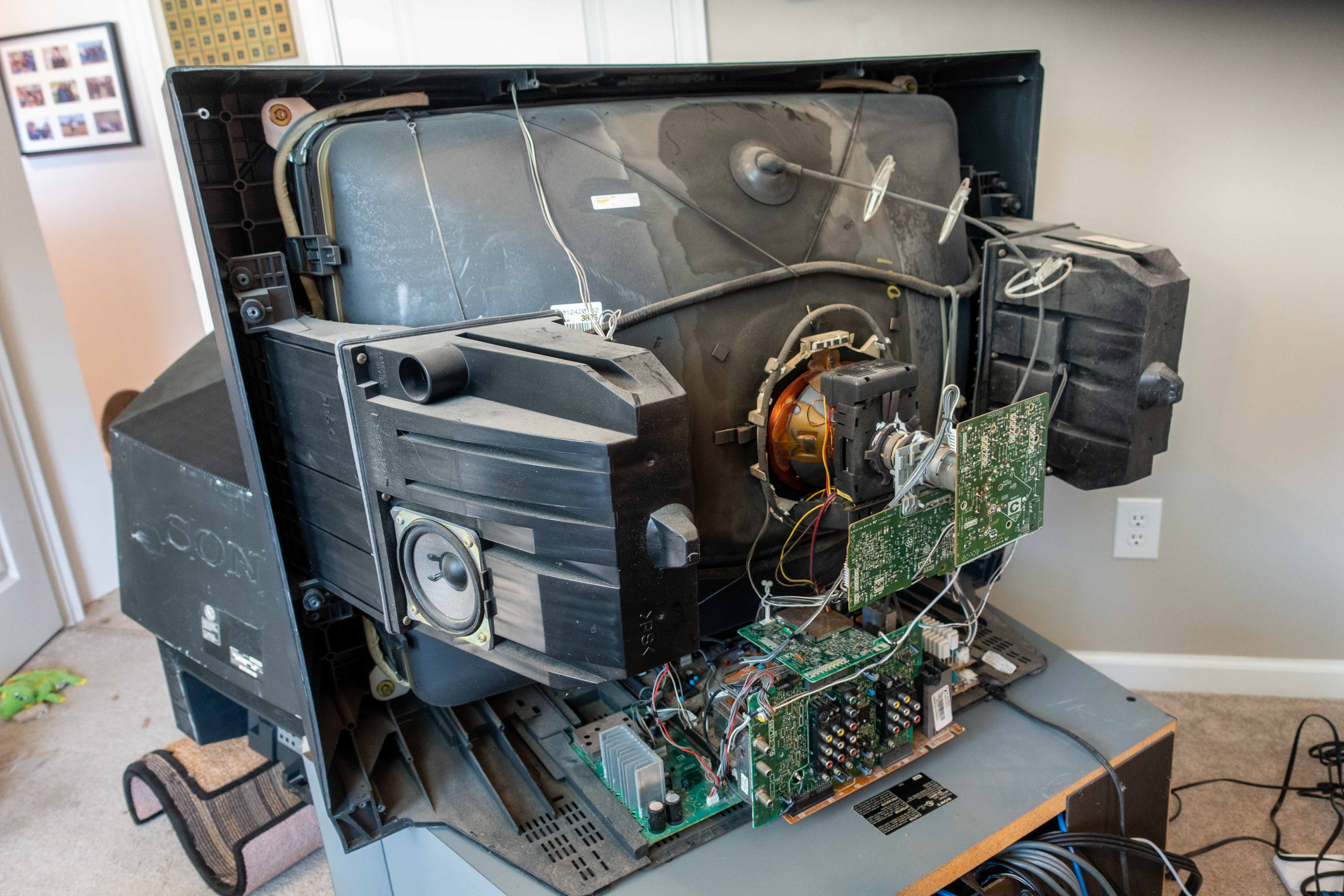
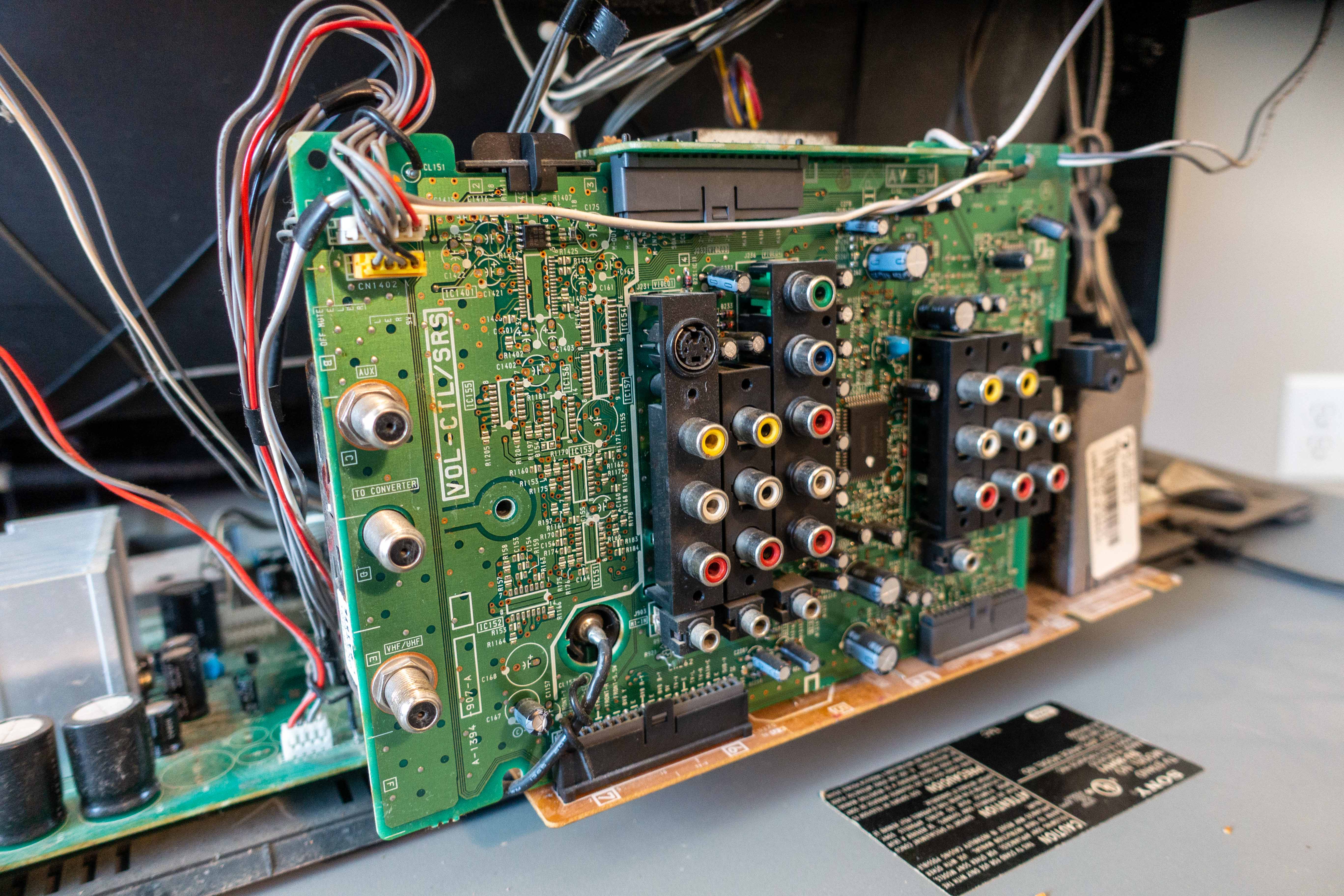
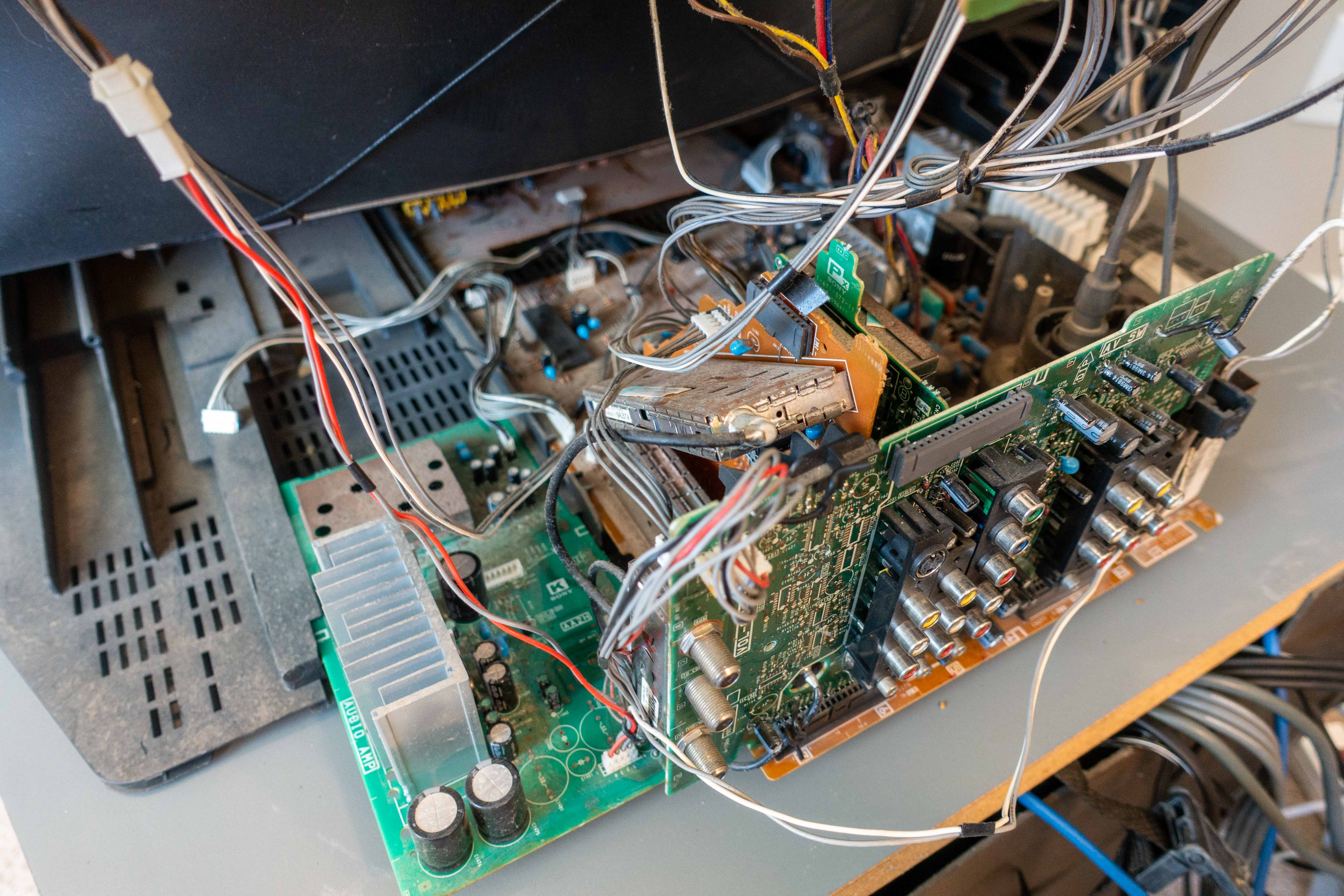
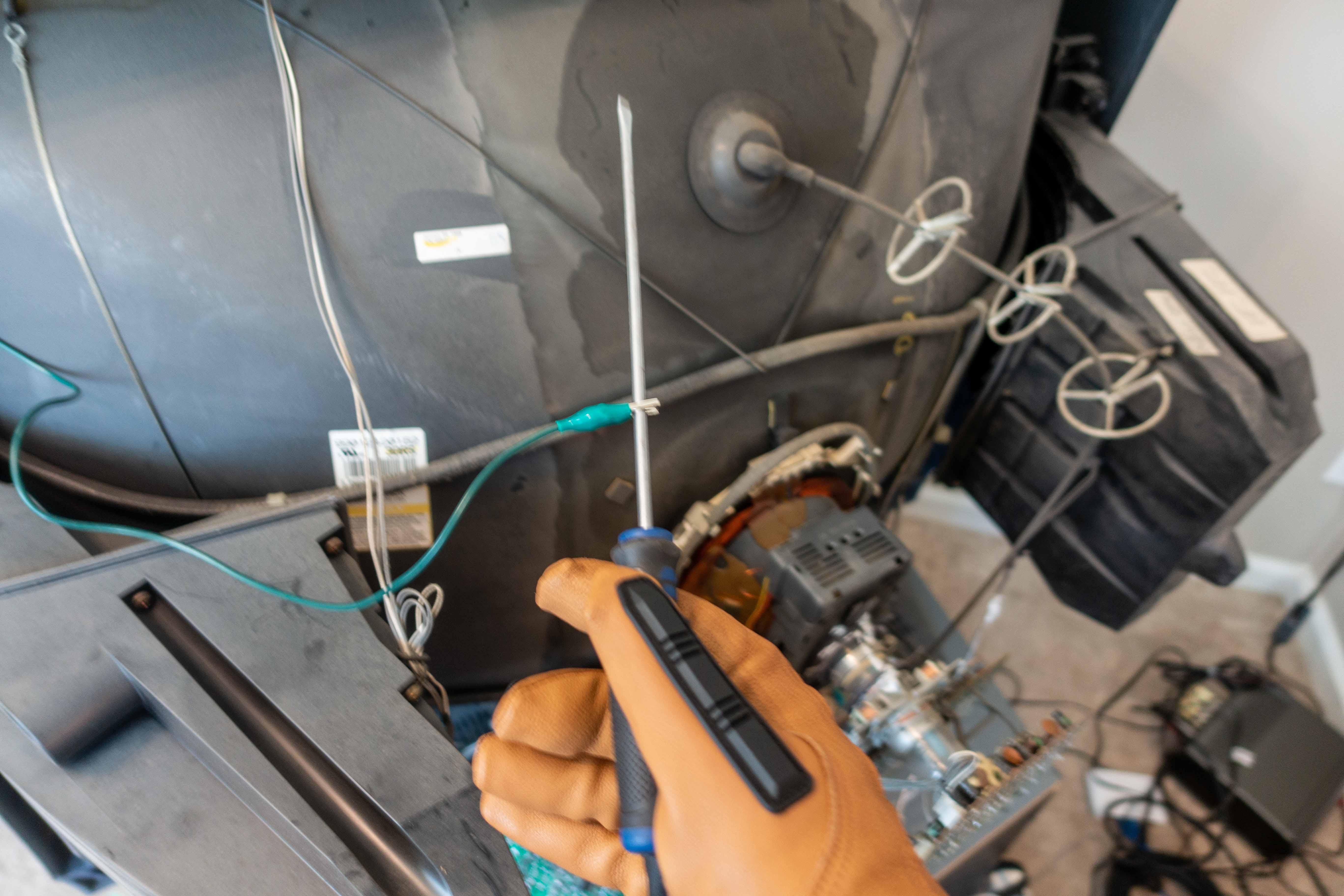
I tried to wiggle things around as much as I could but ultimately there was no avoiding having to deal with the anode. I got some alligator clips to ground a screwdriver and poked around under the little suction cup to discharge the system. If it makes a pop sound, you know you did it right. If it doesn't, then either it was already discharged or you did it wrong and the back of this TV could be the last thing you ever see. My TV did not pop. I did not die. Glorious success.
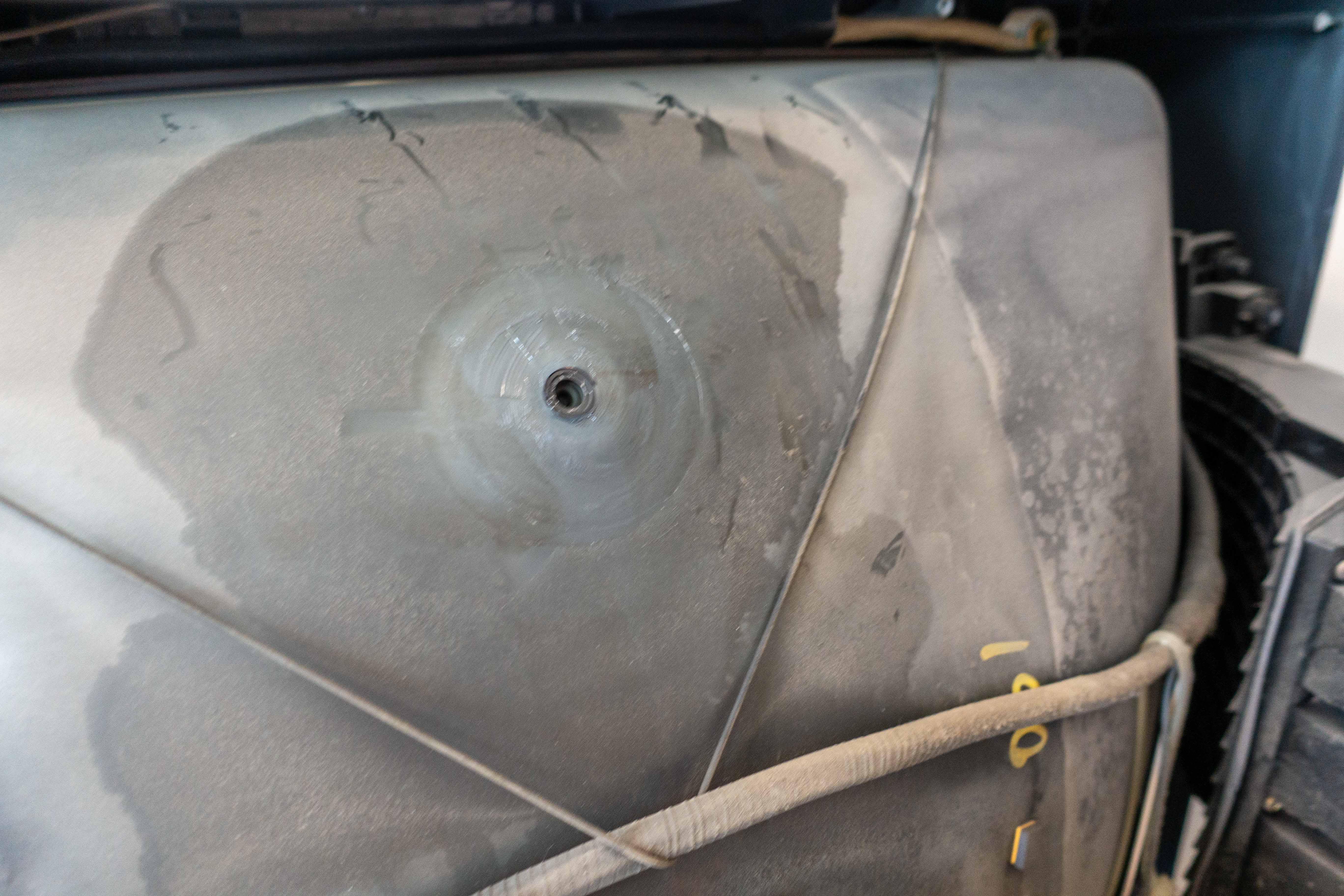
I was able to get the A board all the way out now. It was pretty nasty, so I stuck a shop fan next to it and gave it a quick brushing to get most of the dust off. I also got a closer look at the extent of the damage to the PCB (that would be why my tuner and front I/O aren't working). It's right at the end of where the PCB loses structural support from the plastic frame of the TV, so this is probably the aftermath of a drop.


A Minor Diversion
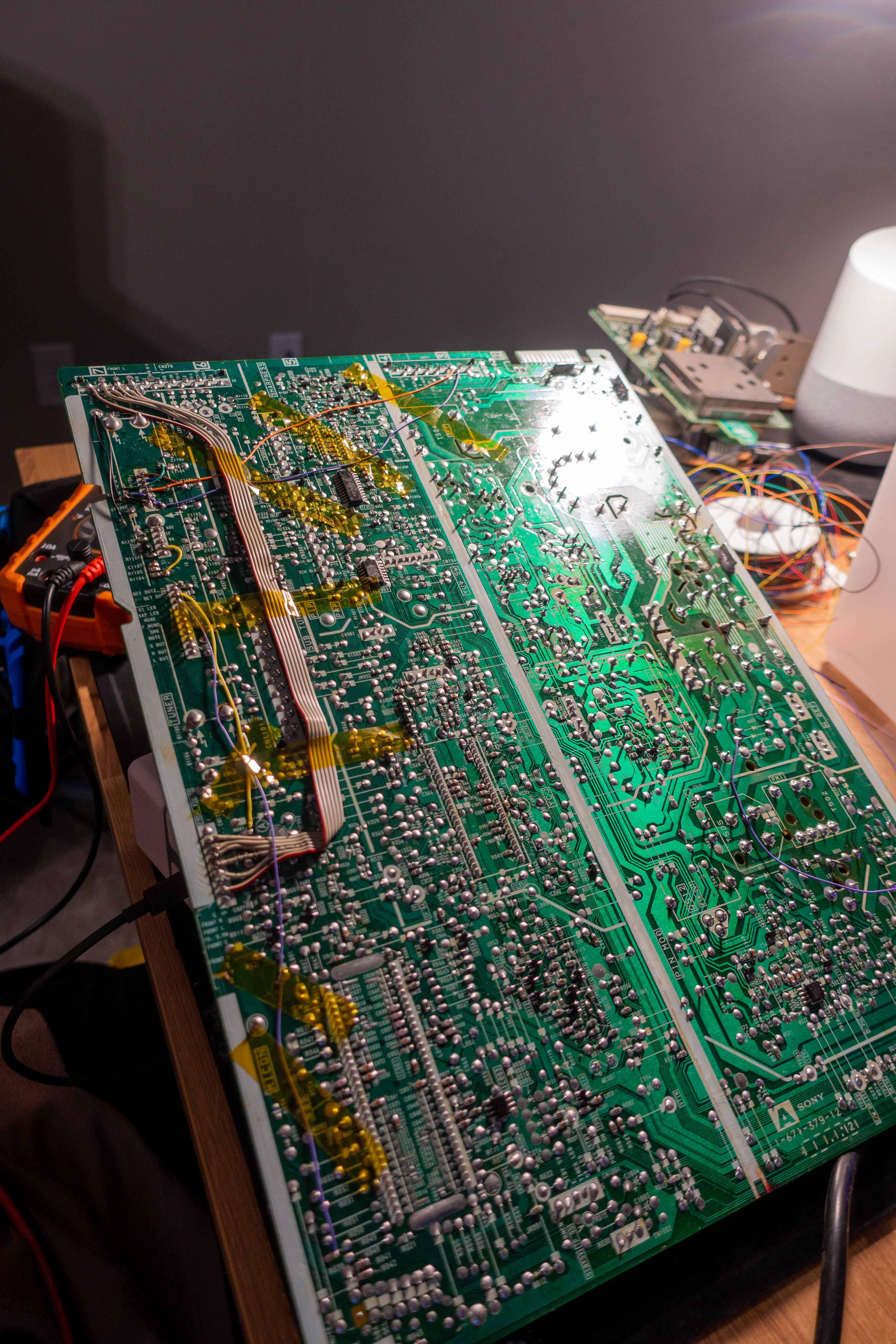
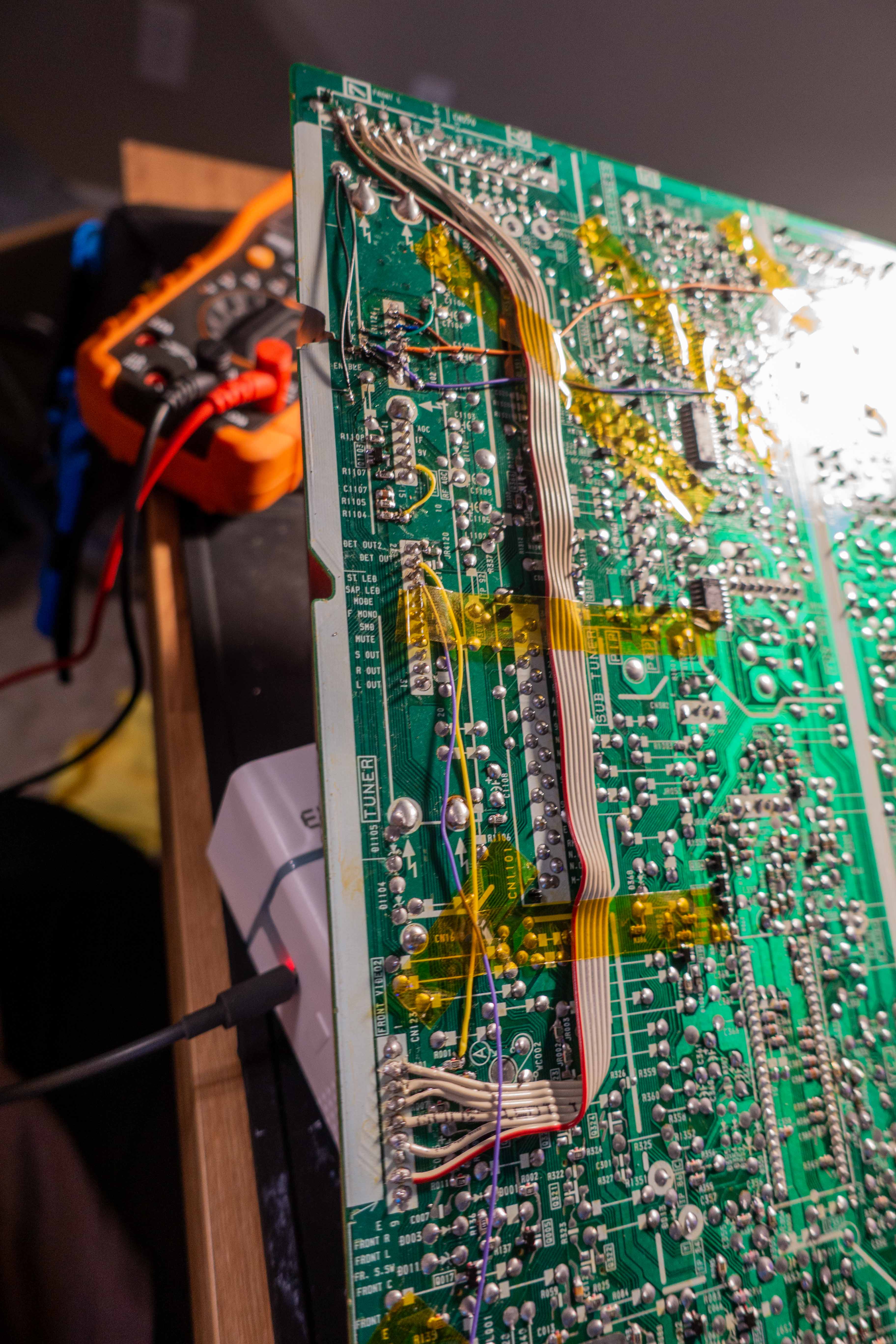
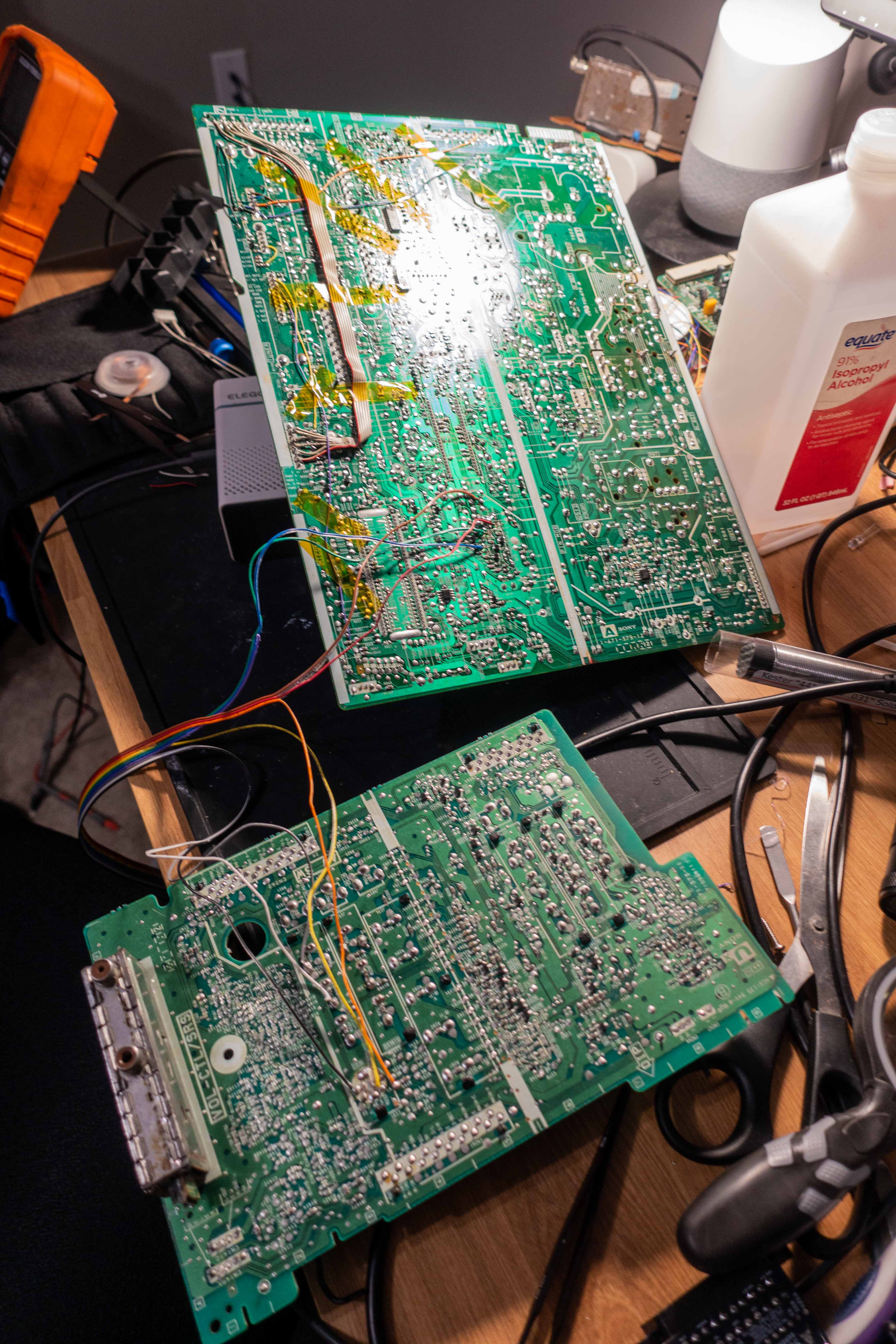
I spent several hours running wires to replace the severed traces from the crack. I would have been totally overwhelmed by this if it weren't for the service manual telling me exactly what each pin on the nearby connectors needed to go to. I probed around with a multimeter to confirm connectivity and replace it where needed. Sadly, I haven't had any luck getting the tuner to work but the front A/V connectors are back in action. I suspect I did something wrong connecting the I2C lines for the tuner and the TV is not able to get it to actually change channels or something along those lines.
Actually Installing the Mod
Alright, with that out of the way, I finally proceeded to doing the actual mod! Since my model varied from the directions I was following from Sunthar's site, it took a bit of staring at schematics to find the right spots for everything.
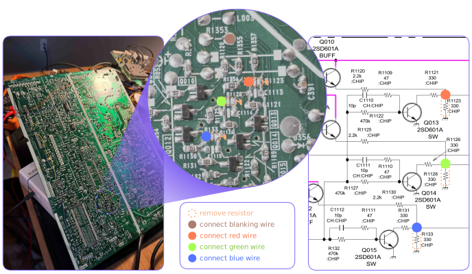
First, let's start with the connections on the A board. There is a group of resistors east of the tuning chip to be removed. The not-connected-to-ground side of these pads are your attachment points for the red (R1123), green (R1128), and blue (R1133) signal wires from the RGB SCART board. It wasn't explicitly said anywhere in the instructions, but the colors on the diagrams correspond to the colors on the ribbon cables provided with the kit. The right side of the nearby R1353 through-hole resistor is the connection point for the blanking interval wire.
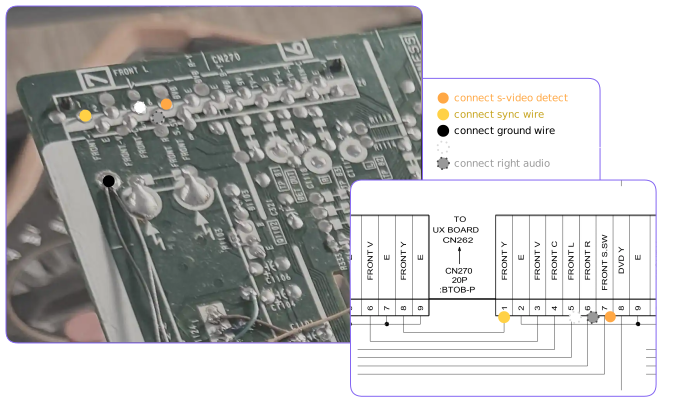
And now the connections on the UX board. You need to sever the connection on the little island marked for the right audio input in order for stereo sound to work. You can see in the photograph where I cut this line on input 3 before realizing I needed to use an input with S-Video. Audio lines for the two channels go to the center plug on each of those. S-Video detect goes to pin 6, ground on pin 2 (or anywhere really), and sync on pin 4 (the luminance input).
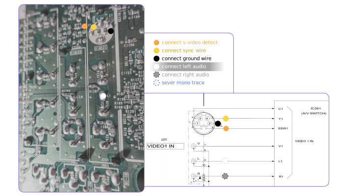
I hijacked my Video 1 input for this, but if I were to do this again, I might elect to tap into Video 2 instead, especially since I hardly ever use the front inputs on the TV. That would also keep all of the wires contained to a single board. Below I have a diagram of how I believe you would wire that up. You'd still need to pull the front I/O board to sever the stereo audio connection.
Other odds and ends, another diode that was included with the kit was added inline with R067 on the top side of the A board. That's everything wired up!

Things Go Awry
And with that, I carefully reassembled the TV to test out the changes. I plugged in my Super Famicom and turned on the power to the TV. I heard it degauss... then, nothing. I was really hoping I didn't just break this thing; I did just solder a whole mess of wires on. I walked around the back of the TV and froze in terror. I had not seated the anode correctly, and it had popped out and was dangling around and fizzling away... menacingly. I don't know if I've ever felt so scared in my life, I still had the jitters for several hours after I finished working on the TV. If I had hair on my arms, it would have been standing on end. I didn't want to stick my hand close enough to the TV to put my little alligator clip on a ground point around the tube, so I went and got a set of jumper cables for a car and used that to discharge the set. There was certainly a pop this time. Forgive me for not taking any pictures during that part; I was a bit preoccupied.
Victory Lap
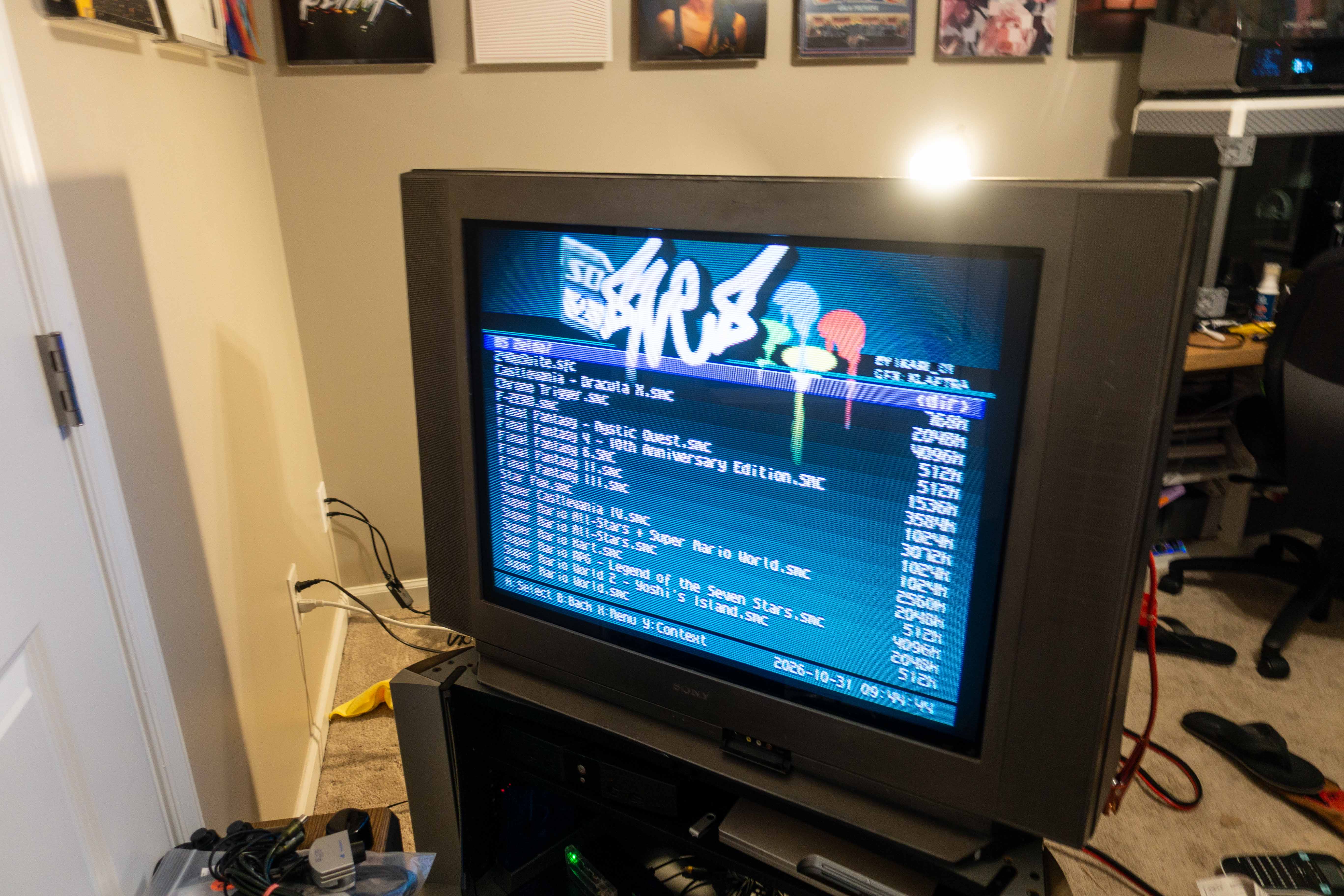
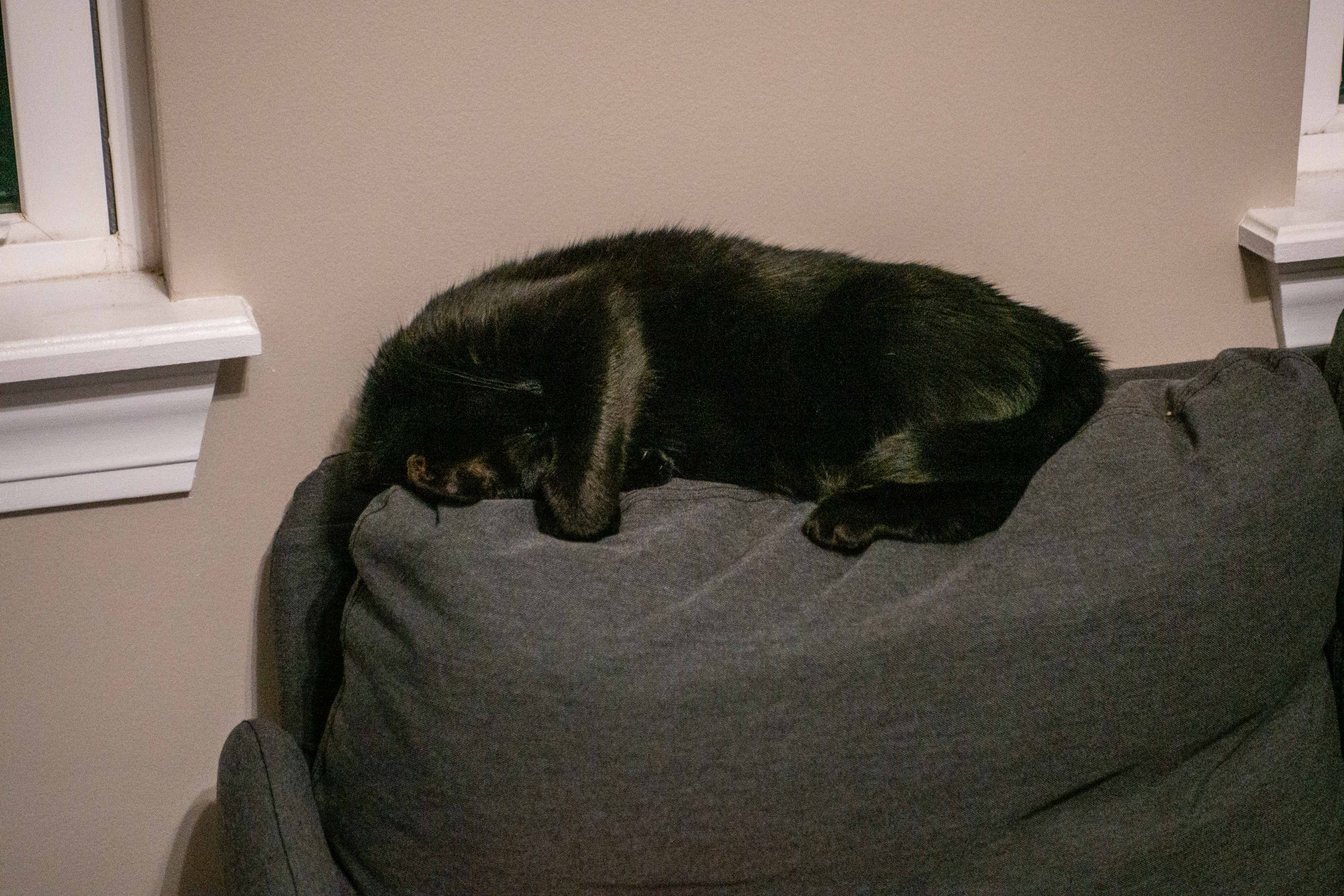
After connecting the anode properly, I tried the TV again, and to my shock (ack!) it was working just fine. I was thinking I would have managed to short something out in my tinkering but the mod was working nicely. I learned that my SFC probably needs new capacitors but found the video to be much cleaner when I connected my PS3 or Dreamcast. My cat was there and she was clearly very impressed by it.
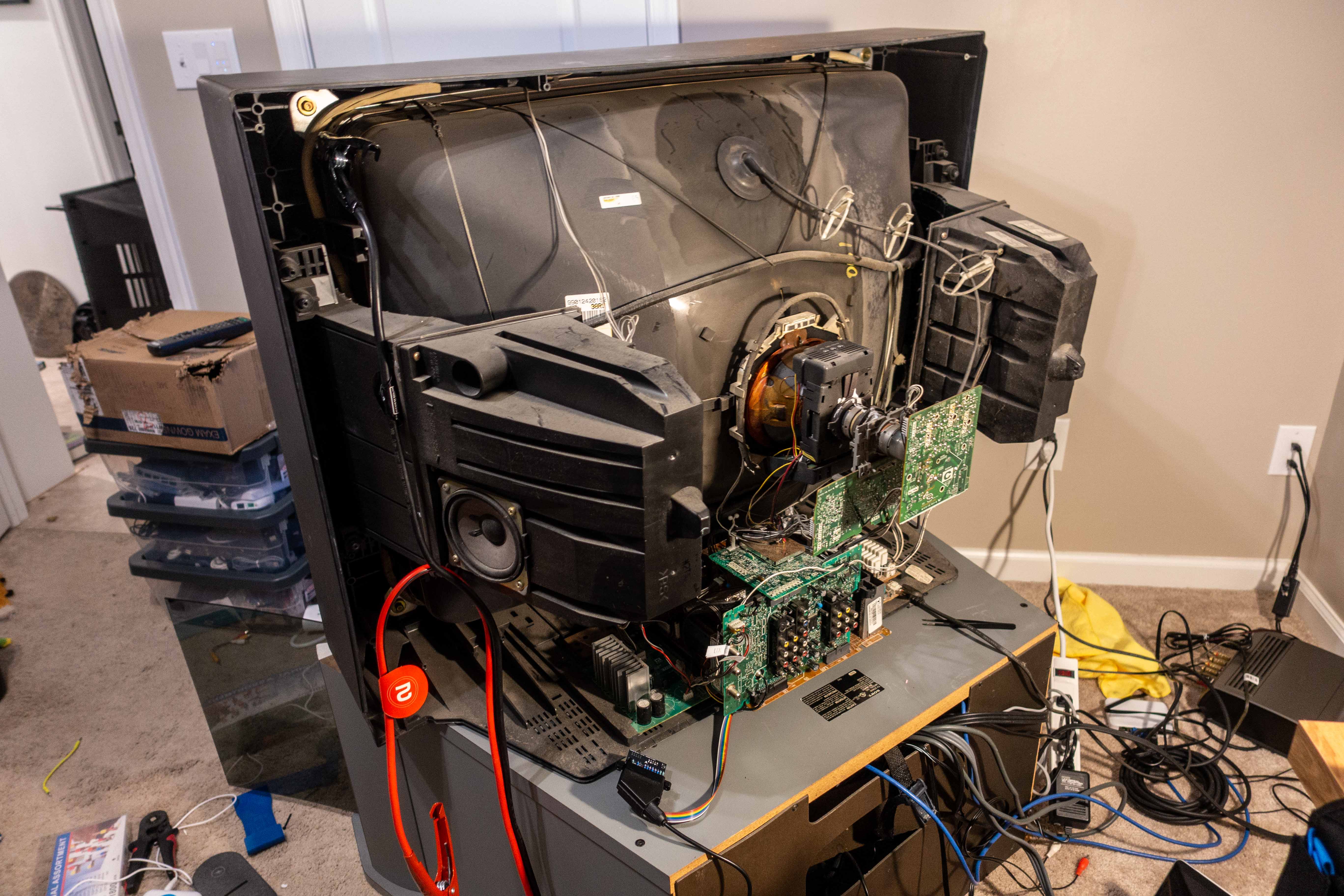
I traced the profile of the SCART connector onto some painter's tape and used that to dremel out a spot to mount the connector. That's the TV back together!


After a bit of readjusting the picture size and pin settings, it was time to relax and enjoy the TV. A very welcome and deserved break from all the stress.
